Ametherm RTE SURGE-GARD™ Thermistors
Quick Overview
Ametherm RTI
manufactures SURGE-GARD™ Inrush current limiting devices using specially formulated metal oxide ceramic materials. These devices are capable of suppressing high inrush current surges. They are especially useful in power supplies where the low impedance of the charging capacitor exposes the diode bridge rectifier to an excessively high current surge at turn-on.
Details
Ametherm SURGE-GARD™ NTC Inrush Current Limiting devices are manufactured using specially formulated metal oxide ceramic materials and certified to UL 1434 for single- and three-phase input voltages to 480VAC. SURGE-GARD devices are capable of handling high steady-state currents to 36A and input energy to 250J. Available with various options in multiple leaded package styles, the components offer resistance at +25°C (R25) from 0.4Ω to 220Ω with tolerances down to ±10%, maximum operating voltage to 265VRMS, and beta from 3000°K to 3965°K.
Ametherm SURGE-GARD™ NTC Inrush Current Limiters
Negative Temperature Coefficient (NTC) thermistors are thermally sensitive semiconductor resistors which exhibit a decrease in resistance as absolute temperature increases. Change in the resistance of the NTC thermistor can be brought about either by a change in the ambient temperature or internally by self-heating resulting from current flowing through the device. Most of the practical applications of NTC thermistors are based on these material characteristics. These RoHS-2 and REACH-compliant Ametherm inrush current limiters are constructed of specially formulated metal oxide ceramic materials and are optimized for a wide variety of applications that require inrush current limiting to reduce noise and circuit failure - including power supplies, motor drives, HVAC motors, transformers, and amplifiers. In these applications, the devices lower costs and increase reliability by eliminating the need to use resistors, timers, and relays.
Applications
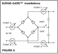
RTI’s SURGE-GARDs™ are used in many applications today that require limiting inrush current when power is applied to a system. The most popular application is the inrush protection of the AC current in switching power supplies (SPS). The primary reason for having surge current suppression in a SPS is to protect the diode bridge rectifier as the input or charging capacitor is initially charged. This capacitor draws significant current during the first half AC cycle and can subject the components in line with the capacitor to excessive current.
The inherent equivalent series resistance (ESR) of the capacitor provides very little protection for the diode bridge rectifier. Use of the proper SURGE-GARD™ will provide maximum current protection when the power supply is turned on and allow the design engineer to select lower peak current rated diode bridge rectifiers for use in their SPS.
If the resistance of one SURGE-GARD™ does not provide sufficient inrush current limiting for an existing application, two or more may be used in series or in separate legs of the power supply circuit. SURGE-GARDs™ should not be used in parallel since one unit will tend to conduct nearly all the current available. SURGE-GARDs™ may be used in the AC input side or in the circuit on the DC line between the charging capacitors and the diode bridge rectifier circuit.
SURGE-GARD Features
- Lowers rectifier cost by reducing required peak forward surge current rating
- Reduces Noise
- Reduces Fuse Failures
- High Current Capacity
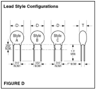
Installation Options
- Thru-Hole Leads
- Insulated/Un-insulated
- Standoffs
- Preformed Leads.
Selection Considerations for SURGE-GARDs™
- IMAX – The first critical consideration in the selection of a SURGE-GARD™ is the maximum steady state current (AC or DC) of the power supply.SURGE-GARDs™ are rated for maximum continuous current. The input power (Pin) is calculated as Pin = Pout/efficiency. In the case of a 75 Watt SPS with 0.70 efficiency, 100% load is calculated to be 107.14 Watts. The maximum input current is at the minimum input voltage. The effective input current (Ie) is equal to the maximum load divided by the minimum input voltage. In this case, a 75 Watt SPS, Ie= Pin/Vin(low)= 107.14 Watts/90 Volts = 1.2 Amps. Therefore, the SURGE-GARD™ must have an IMAX rating of at least 1.2 Amps.
- R@25°C. – The second step is to determine the minimum R value of theSURGE-GARD™ to be selected that will limit the one cycle maximum current rating of the diode bridge rectifier to 50% of its rating to ensure adequate surge protection. Several additional calculations must be made to determine the estimated resistance value required at the point in time of the maximum current surge. RTI provides for a maximum AC voltage rating of 265V RMS on most SURGE-GARDs™. (Reference the Specifications) If the desired maximum inrush current is less than 100 Amps (50% of the diode bridge with a peak current rating of 200 Amps), then solving for R would produce a value of 2.65 ohms. If the MAX Operating Temperatures other than 25°C then the zero power resistance value must be calculated using the NTC Resistance/Temperature Conversion Tables.
- Select a SURGE-GARD™ – The third requirement is to select a SURGE-GARD™ from the specifications. First find the column labeled R@25°C. The resistance values are listed in ascending order. If the exact R value calculated is not listed round up to the next highest R value. In this example that would be a 6 ohm, 5 Amp part, number SG418. Notice that the current rating is higher than required. This current rating is mass dependent therefore the part would be larger in size than the circuit requires. Continue down the column until the closest current rating is located. In this case it would be a 10 ohm, 3 Amp rated part, number SG220. This would be the selected SURGE-GARD™ of choice.
- Evaluate Joules Rating – The fourth step is to review the amount of energy that can be absorbed or dissipated by a SURGE-GARD™ before a failure may occur. The SURGE-GARD™ devices are rated in Joules. In order to calculate the Joules rating the input capacitor value must be specified. Assume that the input capacitor is 220µf. The instantaneous energy is equal to one half times the capacitance of the capacitor plus its tolerance times the peak voltage squared. In this example, Ei = 0.5 (220 (+/-Tol)10-6*(265*1.414)2=15.44 J (nominal). The Joules rating for the SG220 selected is 17J.
(Please note that other criteria such as hold up time, ripple current, capacitor discharge time, and the efficiency of the power supply design may affect the SURGE-GARD™ selection process. Consult RTI’s application engineering personnel for additional information.)
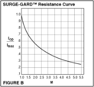
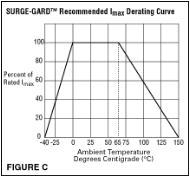
- Calculate IOP/IMAXRatio– Next, estimate the actual operating current,IOP, and calculate theIOP/IMAXratio. The nominal resistance of a SURGE-GARD™ when operated at itsIMAXrating is specified in the Specifications under the RIMAXheading. The device’s resistance when it is operated at a current less than its IMAXrating can be estimated by multiplying itsRIMAXrating by the factor, M. As an example, a SURGE-GARD™with anIMAXof 3.0 Amps and anRIMAXof 0.20 ohms that is operated at 1.2 Amps, theIOP/IMAXcurrent ratio is 1.2 Amps/3.0 Amps = 0.40. The corresponding M factor can be determined from the graph shown in Figure C to be 3.2. Therefore the device’s estimated resistance at 1.2 Amps can be calculated to be R= 3.2 * 0.20 ohms = 0.64 ohms. If two different SURGE-GARDs™ have similar IMAX ratings but different R@25°C values and they meet the circuit requirements, then select the one with the lowestRIMAXnominal value.
- Lastly, if the MAX Operating Temp. range is >65°C or <0°C, refer to the SURGE-GARD™ recommended IMAXDe-rating Curve, Figure C
About Inrush Current Limiter Thermistors
When you switch on an electrical device, it goes through an initial surge of current, also called inrush current. If this surge is too strong, it can harm the device. Inrush Current Limiters (ICLs) work by raising the circuit’s resistance when there’s a lot of current. This reduces the current flow and shields the device.
Many applications, including power supplies, motors, and other devices that experience high inrush currents, frequently rely on ICLs. They play a critical role in safeguarding various electrical devices, preventing damage, and keeping power surges in check.
Here are some advantages of using inrush current limiters:
- Shield devices from damage caused by inrush current.
- Stop power surges.
- Power supplies work more efficiently.
- Act as cost-effective protection.
If you’re designing an electrical device that’s susceptible to high inrush current, it’s a good idea to include an inrush current limiter. It’s a straightforward and effective way to guard your device against potential harm
You may also be interested in the following products
 Ametherm Sensing Thermistors
 Ametherm's Mini-Amp Thermistors / Inrush Current Limiters