ATE PR Series Thick Film Power Resistors
Quick Overview
ATE Electronics PR Series Thick Film Power Resistors
ATE PR-series Thick Film Power Resistors provide high rated power, excellent load life stability, and low TCR. PR Series providing you with the widest selection of highly precise and reliable foil resistors from made-to-order to standardized, that meet any required qualifications.
Details
PR-series Thick Film Power Resistors: Every designer that works with electronic components knows well integration system, reliability and custom products problems. ATE Electronics solves these problems since 1970 producing power resistors with high quality and technology.
- Ideal for snubber and filter application
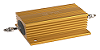
- Compact housed resistors with excellent heat conduction
- Must be used with external heatsink
- Molded housing which can withstand strong environmental condi- tions
- Optimized construction with high thermal conduction
- Large creep distance
- All internal electrical connections are welded
Thick film resistors PR series
Applications
Thick Film Resistors are ideally suited in electrical filters and snubbers because of their low parasitic inductance and easy to use. PR thick film resistors must be mounted on a heatsink to take full advantage of their power ratings. The base place is electrically insulated. No additional insulation foil is required. Thermal grease is neccessary to provide a good thermal contact between resistor base an heatsink. Recommen- ded is a conductivity of 1W/mK or better. PR series are available in 4 housing types and 4 power ratings, ranging from 100W to over 800W.
Construction
Thick Film Resistors are produced by firing a special paste onto an alumina ceramic substrate. The electrical connections are tin welded to the thick film through copper wire, making a stable connection. The substrate on the bottom side has a metal finish (PR 250) to minimize partial discharge. The substrate is slightly outside the molded hou- sing. When the housing is mounted to the heat sink, sufficient force for pressing the substrate to the heat sink is automatically applied. All materials are UL94-V0 listed.
Mounting
The thick film resistors must be mounted on a heat sink. Between the heat sink and the resistor module, a thin layer of thermal grease must be applied (60—100 micrometers). Alternatively, high quality, ther- mal conductive, non-electrical insulating foils can be used. For proper mounting, please consult the mounting instructions. Mounting screws and washers are included.
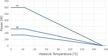
De-rating
The nominal power depends on the heat sink temperature. When the re- sistor is used at higher temperatures, the nominal power must be linear- ly de-rated. Graph 1 and 2 give the nominal power values for PR100 and PR250, based on heatsink temperature. Graph 3 and 4 give the nominal power for PR600 and PR800, based on resistor base temperature.
Heat sink requirements
Depending on the total power which needs to be dissipated, a correct heat sink must be used. The maximum power the resistor can dissipate depends on the heat sink temperature and with that, on the thermal resistance of the heat sink and ambient temperature. The surface where the resistor will be mounted needs to be machined to a planarity of 50 micrometer and roughness of less than 6.3 micrometer.
|
General specifications |
remark |
PR100 |
|
Power rating |
PR100 |
100W |
|
|
PR102 |
2x50W |
|
Max power |
not trimmed |
150W |
|
Resistance range |
E12 |
1R0 to 1M0 * |
|
Tolerance |
standard |
10% |
|
|
optional |
up to 1% |
|
Temperature coefficient |
|
±100ppm/K |
|
Max working voltage |
|
1500 VAC |
|
Working temperature range |
|
-55°C - +155°C |
|
Dielectric strength |
1 minute 50Hz |
2500VAC |
|
Insulation resistance |
@ 500V |
> 105 MΩ |
|
Partial discharge |
on request |
< 80pC @ 2000VAC |
|
Self inductance |
|
40nH |
|
Capacitance to heatsink |
|
< 30pF |
|
Overload |
10s |
2xPn |
|
Thermal resistance |
|
0.5K/W |
|
Heatsink flatness |
|
0.05mm |
|
Heatsink surface finish |
|
6.3μm |
|
Max torque for contacts |
|
1.2Nm |
|
Max torque for mounting |
|
1.5Nm |
|
Weight |
PR100/PR101 |
18g |
|
|
PR102/PR103 |
24g |
|
General specifications |
remark |
PR250 |
|
Power rating |
@ heatsink 100°C |
250W |
|
Max power |
not trimmed @ 70°C |
500W |
|
Resistance range |
E12 |
1R0 to 1M0 * |
|
Tolerance |
standard |
10% |
|
|
optional |
up to 1% |
|
Temperature coefficient |
|
±100 ppm/K |
|
Max working voltage |
|
5000 VAC |
|
Working temperature range |
|
-55°C - +155°C |
|
Dielectric strength |
PR250 |
7000VAC |
|
|
PR250T |
12000VAC |
|
Insulation resistance |
@ 500V |
> 105 MΩ |
|
Creepage distance |
PR250 |
42mm |
|
|
PR250T |
65mm |
|
Airgap distance |
PR250 |
16mm |
|
|
PR250T |
29mm |
|
Partial discharge |
|
< 10pC @ 5000VAC |
|
Self inductance |
|
80nH |
|
Capacitance to heatsink |
|
< 120pF |
|
Overload |
10s |
4xPn |
|
Thermal resistance |
|
0.15K/W |
|
Heatsink flatness |
|
0.05mm |
|
Heatsink surface finish |
|
6.3μm |
|
Max torque for contacts |
|
2Nm |
|
Max torque for mounting |
|
2Nm |
|
Weight |
PR250 |
100g |
|
|
PR250T |
130g |
|
Cable terminals |
optional |
|
* For out of range or non-standard values, please contact
Heatsink calculation
PR resistors series must be mounted on a heatsink to take full advantage of the power capa- bility. The maximum thermal resistonace of the heatsink can be calculated by the following formula: 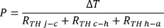
P is dissipated power in the resistor in Watts.
ΔT is the difference between maximum working temperature (155°C) and room temperature. RTH j-c is the thermal resistance of the resistor between junction and case.
0.5K/W for PR100 and 0.15K/W for PR250
RTH c-h is the thermal resistance between the base plate of the resistor and the heatsink This value is determined by the thickness and the properties of the paste, and
the surface arrea size. Recommended is a paste with conductivity of 1W/mK or better.
RTH h-a is the thermal resistance of the heatsink to ambient. This value is given by the manufacturer of the heatsink.
|
General specifications |
remark |
PR600 |
PR800 |
|
Power rating |
@ Bottom base 85°C |
600W |
800W |
|
Max power |
consult |
700W |
950W |
|
Resistance range |
E12 |
1R0 to 1M0 * |
|
|
Tolerance |
standard |
10% |
|
|
|
optional |
up to 1% |
|
|
Temperature coefficient |
|
±100 ppm/K |
|
|
Max working voltage |
|
5000 VAC |
|
|
Working temperature range |
|
-55°C - +155°C |
|
|
Dielectric strength |
standard |
7000VAC |
|
|
|
on request |
12000VAC |
|
|
Insulation resistance |
@ 500V |
> 105 MΩ |
|
|
Creepage distance |
|
42mm |
|
|
Airgap distance |
|
16mm |
|
|
Partial discharge |
|
< 10pC @ 5000VAC |
|
|
Self inductance |
|
80nH |
|
|
Parallel capacitance |
|
40pF |
|
|
Capacitance to heatsink |
|
< 110pF |
< 150pF |
|
Overload |
10s |
1kW |
|
|
Thermal resistance |
|
0.115K/W |
0.11K/W |
|
Heatsink flatness |
|
0.05mm |
|
|
Heatsink surface finish |
|
6.3μm |
|
|
Max torque for contacts |
|
2Nm |
|
|
Max torque for mounting |
|
2Nm |
|
|
Weight |
|
95g |
100g |
Pulse load / overload capability.
PR series resistors can be overloaded during a certain time. The energy the resistor can take is in relation to the duration of the overload. For repetitive overloads, a minimum cooldown time must be observed before the resistor can take another pulse load.
For high demands on overload capbilities, metal thick film versions are available.
You may also be interested in the following products
 ATE Electronics PR-Series Power Resistors ATE Electronics PR-Series Power Resistors
|
 ATE Electronics RB Series Power Resistors ATE Electronics RB Series Power Resistors
|